How to Calibrate Your MPI Equipment in 5 Steps

  •  

In this article, we will go over the five key factors to successfully calibrate your Magnetic Particle Equipment in reference to ASTM E1444, ASTM E3024, ISO 9934, or Nadcap AC7114/2

by David Geis, Product Manager, and Brian Batteiger, NDT Services Manager

There are many different types of magnetic particle equipment, ranging from small portable power packs to wet bench units, all the way to high-amperage stationary power packs for large structures.

If you are following ASTM E1444, ASTM E3024, ISO 9934, or Nadcap AC7114/2, your equipment must be calibrated on a semi-annual basis. No matter what type of magnetic particle equipment you have, and no matter which specification you follow, the same five steps are used to perform equipment calibration.
 

Understand the difference between magnetic particle inspection standards ASTM E709, ASTM E1444 and ASTM E3024 in this quick guide.


Step 1: Verify your standards

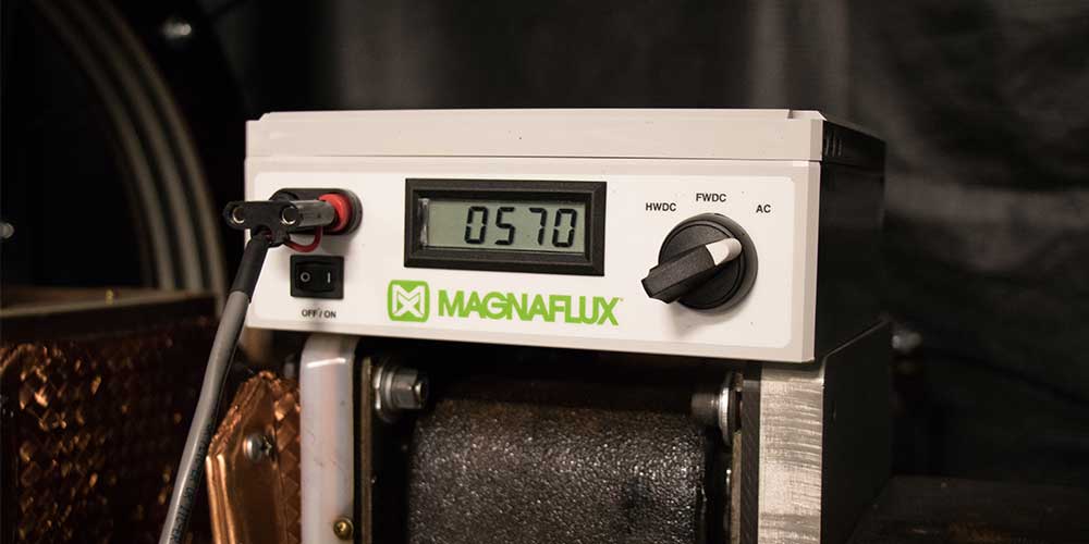
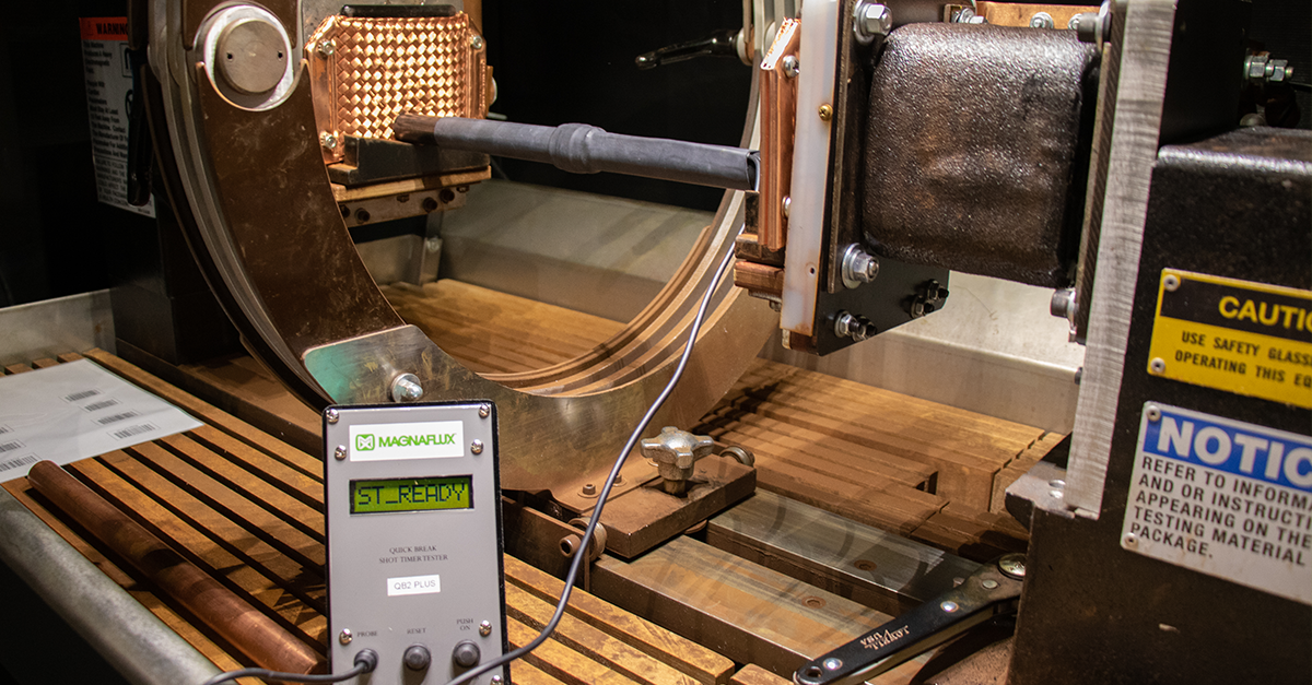
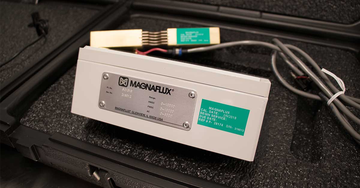
  1. Standard reference meters needed to do the job: Shunt, Ammeter, and Shot Timer. For 3-phase FWDC units, a Quick Break Tester is also required. Different meters have different controls. Refer to the instructions for your standard reference meters for detailed operating procedures.
     
  2. Check calibration date of reference meters – were they all calibrated within the past six months?
     
  3. How much data is required? The total amount depends on the configuration of your equipment. Data should be collected for each waveform (AC, HWDC, FWDC) the equipment can generate, and for each output channel (contact, coil, auxiliary) the equipment has.


Step 2: Ammeter accuracy

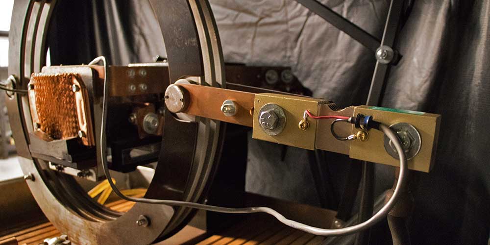
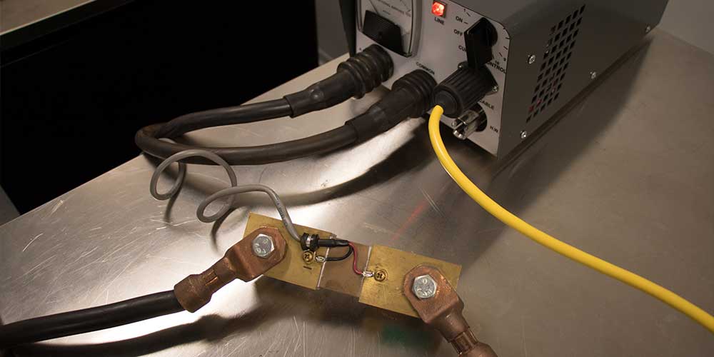
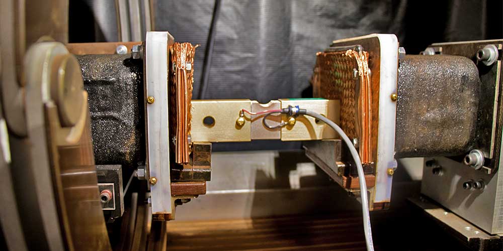
  1. Connect reference shunt in series with output circuit and connect leads to reference ammeter
     
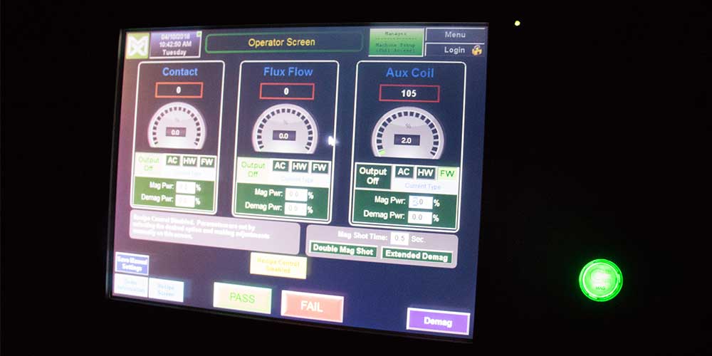
  2. Set mag shot amperage to the middle of the equipment operating range
     
  3. Initiate mag shot and log reading of both the equipment ammeter and the reference ammeter
     
  4. Calculate the difference between readings and compare to tolerance (+/- 10% or 50 A whichever is greater)
     
  5. Repeat at a minimum of three set points across the usable range of the equipment
     
  6. Repeat the procedure for each waveform (AC, HWDC, FWDC) on that output channel
     
  7. Repeat the full procedure for each output channel (contact, coil, auxiliary) on the equipment
     

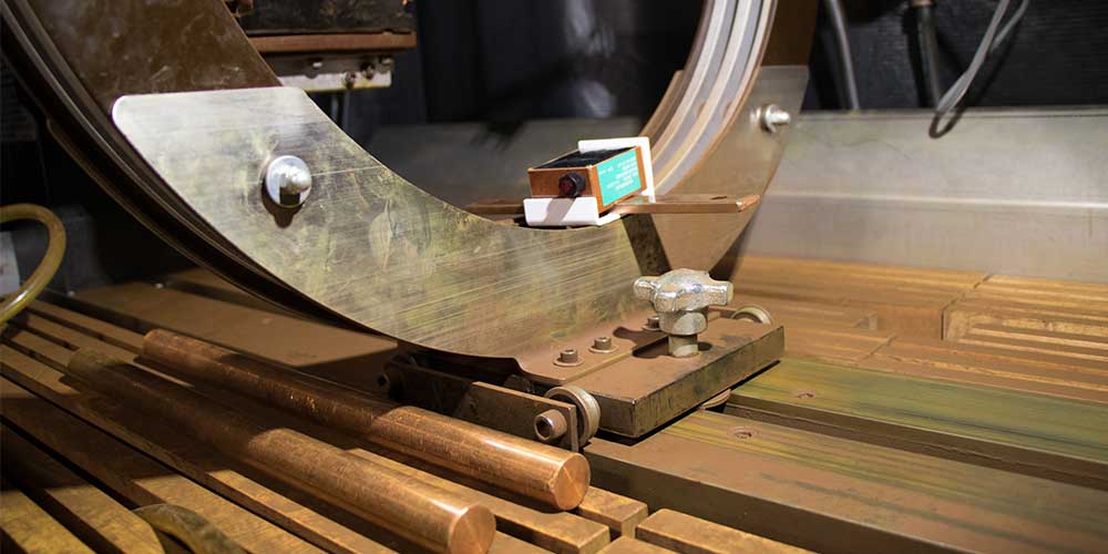
For contact shots, clamp the shunt between the headstock and tailstock


For coil shots, connect the shunt in series with the bench coil


For cable wraps and portable power packs, connect the shunt in series with the cable


Step 3: Equipment repeatability

  1. Set mag shot to lowest amp setting used
     
  2. Initiate mag shot and log reading on the equipment ammeter
     
  3. Determine tolerance and acceptance range for repeated shots (+/- 10% or 50 A whichever is greater)
     
  4. Repeat the mag shot until a minimum of six readings have been collected, comparing each reading to established acceptance range
     
  5. Repeat the procedure for each waveform (AC, HWDC, FWDC) on that output channel
     
  6. Repeat the full procedure for each output channel (contact, coil, auxiliary out) on the equipment


Step 4: Shot Time

  1. Follow the specific instructions for your meter to set it up on your equipment
     
  2. Set mag shot amperage to the middle of the equipment operating range
     
  3. Initiate mag shot and log reading on shot timer
     
  4. Reading should be within +/- 0.1 sec to the set mag shot time
     
  5. Repeat the procedure if your equipment has separate controllers for each output channel


Step 5: Quick Break for 3-phase FWDC units only

  1. Place the Quick Break sensor inside the equipment coil, and follow the specific instructions for your meter. Quick break is only valid for 3-phase FWDC units, and only valid for coil shots or cable wraps.
     
  2. Set mag shot to deliver 15,000 Amp-Turns
    • For a 5-turn bench coil, set equipment for 3,000 A
    • For 3-turn coil wrap, set equipment for 5,000 A
       
  3. Initiate mag shot and observe results on the Quick Break Tester
    • Go/No-Go Gauge: Observe lamp flash during shot. The lamp may flash at the start of the mag shot, at the end, or both. Any flash is a positive result. Repeat up to 20 times; the lamp should flash for at least 80% of the mag shots. Go/No-Go Gauges are only valid for use with coils up to 25 in / 63.5 cm diameter.
    • Digital meter: Compare reading to Quick Break voltage table. Minimum acceptable reading depends on the diameter of the coil

Coil Diameter (in / cm) Minimum Quick Break Voltage
12 / 31 8
16 / 41 6
20 / 51 4
25 / 64 3
30 / 76 2
36 / 91 1


Following these five steps will allow you to calibrate your magnetic particle equipment. Be sure to maintain records of the calibration data to demonstrate compliance with ASTM, ISO, and Nadcap requirements.


Published May 22, 2018


Regular upkeep on mag particle equipment is critical for non-destructive testing to safe guard inspections & reduce downtime. Learn How to Do Preventative Maintenance for Magnetic Particle Equipment.

Please wait while we gather your results.

Related Blog Posts

3 Reasons to Try the Y-2 Yoke

3 Reasons to Try the Y-2 Yoke [Video]

Explaining mag particle scenarios in the field, and how they can be changed depending on the yoke selection

Read More...

5 Things to Consider When Choosing a Mag Particle Yoke [Checklist]

5 Things to Consider When Choosing a Mag Particle Yoke [Checklist]

In this article we outline some key factors to consider when selecting the right electromagnetic yoke or contour probe for magnetic particle testing

Read More...

Subscribe to Magnaflux News:

Magnaflux

Faraday Road, South Dorcan Industrial Estate
Swindon, Wiltshire, SN3 5HE, UK
Telephone: +44 (0)1793 524566
Contact Magnaflux Customer Service

Magnaflux, A Division of ITW Limited   VAT number: GB 531 8325 59

Select Your Country North America Mexico Brazil China Europe India New Zealand, Australia, Japan, Southeast Asia
© 2024 Magnaflux - All Rights Reserved.
top